


ASE62056 Meter Simulator
ASE62056 Meter Simulator enables utility to evaluate HES/MDMS during their AMI project’s vendor selection stage or integration phase and identify issues before full meter deployment as well as to perform comparative assessment of different HES/MDMS systems.
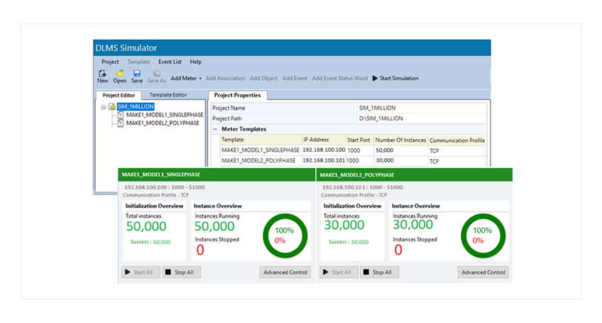
Some of the smart metering use cases which would be difficult or impossible using meters in operation can be simulated there by assisting end-users to make informed decisions. HES/MDMS developers can use Simulator for demonstrating capabilities and scalability of their HES/MDMS as well as for In-house validation and performance benchmarking.
Overview
The ASE62056 Meter Simulator enables utilities, system integrators, and Head End System manufacturers to run use cases and evaluate various key performance indicators, including:
- Data acquisition time
- Communication failure rate
- Command execution success rate
- Firmware upgrade time
- Alarm / Event real-time notification handling efficiency
The tool allows users to simulate negative and very large/boundary values as well as data gaps in meters to verify HES/MDMS validation functions. Various practical communication issues, such as network delays, meter going offline, can be simulated to assess the impact on overall data acquisition time.
ASE62056 Simulator, when used for single-meter simulation, enables the developers and testers to overcome the unavailability of real meters during the development phase of any project. Key advantages are:
- Cloning of a meter and simulation
- Creation of a custom meter configuration and simulation
- Multiple DLMS client users can connect to a single simulator
- Traffic & Log module facilitates simulation and debugging of communication issues
This tool allows DLMS operations that are not possible using real meters, such as simulating large/boundary values, negative conditions, timeouts, and different types of security. A reduced development time for meters, meter interface cards, data concentrators, and head-end systems.
Factsheets
| Data (IC: 1 v0) | Image Transfer (IC: 18 v0) |
| Register (IC: 3 v0) | Activity Calendar (IC: 20 v0) |
| Extended Register (IC: 4 v0) | Limiter (IC: 71 v0) |
| Profile Generic (IC 7 v1) | Push setup (IC: 40 v0) |
| Clock (IC: 8 v0) | Security setup (IC 64 v0, v1) |
| Clock (IC: 8 v0) | Security setup (IC 64 v0, v1) |
| Script table (IC: 9 v0) | Disconnect control (IC 70 v0) |
| Association LN (IC: 15 v0, 1, 2, 3) | Single Action Schedule(IC: 22 v0) |
| Simulation Type | IC 1 | IC 3 | IC 4 |
|---|---|---|---|
| Invocation counter | ✓ | ||
| Serial number | ✓ | ||
| Constant | ✓ | ✓ | ✓ |
| Step | ✓ | ✓ | ✓ |
| Cumulative | ✓ | ✓ | ✓ |
| Scaler Unit | ✓ | ✓ | |
| Max Demand | ✓ | ||
| Capture time | ✓ |
| SIMULATION TYPE | IC 7 | IC 8 | IC 20 | IC 22 | IC 70 | IC 71 | IC 40 |
|---|---|---|---|---|---|---|---|
| Time | ✓ | ||||||
| Time write/sync | ✓ | ||||||
| Connect/Disconnect | ✓ | ✓ | ✓ | ✓ | ✓ | ||
| Limiter threshold read and write | ✓ | ||||||
| TOU – read and write | ✓ | ||||||
| Scheduled data push | ✓ | ✓ | |||||
| Scheduled profile capture | ✓ | ✓ | |||||
| Event based profile capture | ✓ | ✓ |
| Simulation Type | IC 15 | IC 64 | IC 18 |
|---|---|---|---|
| LLS password change | ✓ | ✓ | |
| HLS Key change | ✓ | ✓ | |
| Global encryption key change | ✓ | ||
| Authentication key change | |||
| Firmware update | ✓ |
- No authentication, LLS, HLS 2, 3, 4, 5
- Security suite 0, suite 1
- HDLC
- IP (v4 and v6)
- Logical Name without ciphering
- Logical Name with ciphering
